Skip to content
Rocklok® Segmental Retaining Wall system, proudly developed in New Zealand, has gained popularity among retaining wall contractors and landscapers for its unique features and benefits. One of its standout characteristics is its near vertical setback, which refers to the angle at which the wall inclines backward. This design contributes to the system’s visually appealing finish.

The Rocklok system is known for its structural integrity and durability. It features a pin-block connection that is exceptionally robust, leading to superior wall performance. This connection mechanism ensures that the individual segments of the retaining wall interlock effectively, enhancing stability and load-bearing capacity.

One of the notable features of Rocklok® is its versatility in terms of reinforcement options. It can be mechanically connected with High-Density Polyethylene (HDPE) geogrids. The system has been tested in conjunction with steel ladders, especially in scenarios requiring inextensible reinforcement, such as bridge abutments. This demonstrates the system’s adaptability to diverse engineering requirements.

The positive connection established by the Rocklok® system offers added performance benefits, particularly in situations involving critical loads and seismic conditions. This is crucial for projects located in areas prone to earthquakes or other ground-related disturbances.
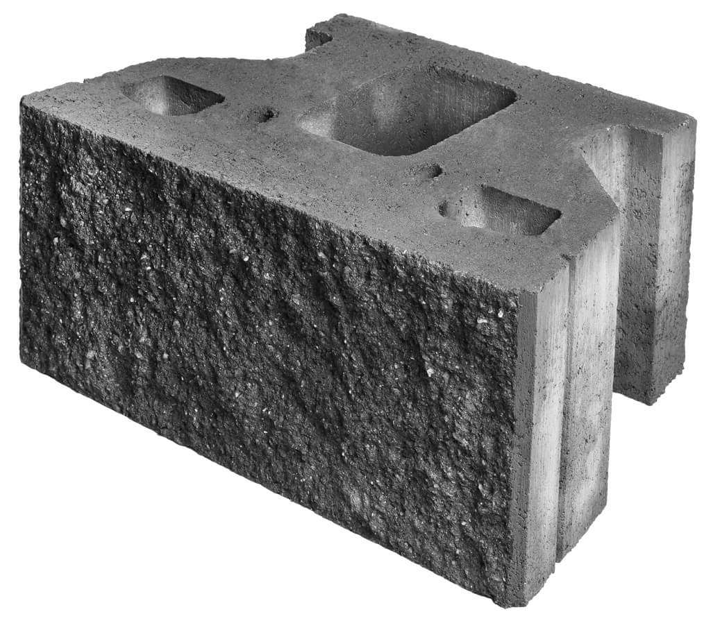
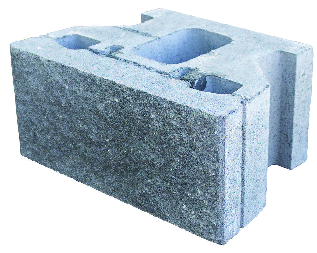
Rocklok Product Image

This product is not subject to a warning or ban under the Building Act 2004, or a description of any warning or ban that has been made in relation to the product.

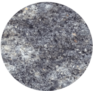
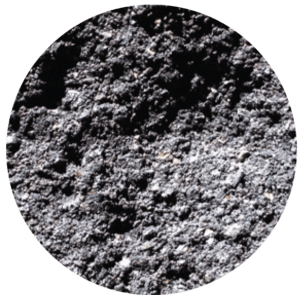
Colours

*Made to order colours and finishes are available on a minimum order quantity.
Please talk to your local Bowers representative for more information.

Download a Brochure

Get inspired or learn more about what our products can do for you with our comprehensive list of brochures.

Technical Specifications

Download installation guides, spec books and product manuals.

CAD Details & Drawings

Download CAD details & technical design drawings for this product.

Specifications

Rocklok® Flat


Dimensions

450mm L x 300mm D x 200mm H

Coverage

11.1 block/m2

Quantity

40 blocks/pallet

Setback

1° setback from vertical

Weight

39.5 kg/block

Rocklok® Trench


Dimensions

450mm L x 300mm D x 200mm H

Coverage

11.1 block/m2

Quantity

40 blocks/pallet

Setback

1° setback from vertical

Weight

40.5 kg/block

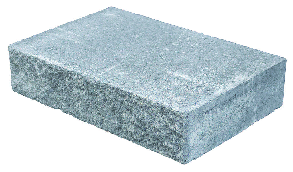
Rocklok Capstone


Dimensions

450mm L x 300mm D x 100mm H

Coverage

2.2 block/lm

Quantity

63 blocks/pallet

Setback

N/A

Weight

27.5 kg/block

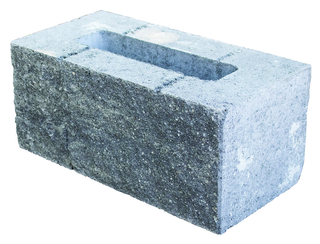
Rocklok End/Corner


Dimensions

400mm L 225mm D x 200mm H

Coverage

N/A

Quantity

40 blocks/pallet

Setback

N/A

Weight

38 kg/block

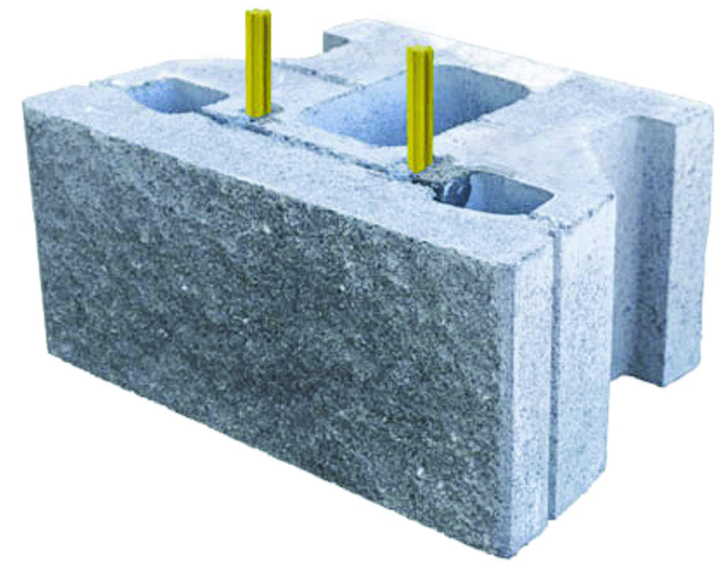
Rocklok Fiberglass Pins*


Dimensions

135mm L x 16mm diameter

Coverage

40 pins/box

Quantity

*Each Rocklok Flat block requires 2 Rocklok Fibreglass Pins

Setback

Weight

Benefits of this system

Services provided for this system

Bowers Retaining Wall Systems Range

Bowers are the trusted name in masonry… We manufacture all our retaining wall products in the Waikato and have generous stock levels to accommodate any retaining project Commercial or Residential. Our experience team are available to assist with wall designs, training and installation.

Frequently Asked Questions

Question

What is the Rocklok® system setback?  

Answer

The Rocklok® system batter angle approximately 1° from vertical, sloping towards the infill soil.

Question

How many pins do I need?  

Answer

Two Ø16mm fibreglass pins are required per Rocklok® unit, except those units that form the top course where the Rocklok® Capstone unit sits on.

Question

Can I replace the Rocklok® fibreglass pins for other pins or equivalent products?  

Answer

No. The pins and the Rocklok® ® blocks are part of a system and they must be used in combination. Pins are not interchangeable with similar products or components from other retaining systems. Cost, performance, and safety may be affected by the use of elements not certified by Bowers Brothers Concrete Limited.

Question

What advantage do the Rocklok® pins have compared to the pins used in other systems?  

Answer

The Rocklok® fibreglass pins have a bigger diameter than other common pins, which normally are 12 to 14 mm. The 16 mm diameter pins provide extra shear strength compared to smaller diameter pins.

Question

What are the recommendations for the base levelling pad?  

Answer

We recommend you have a minimum base levelling pad size of 600 mm width and 150 mm depth. We believe that either GAP 20 or GAP 40 are probably the best options.

Question

How many Rocklok® units should be buried as embedment?  

Answer

The SRW Best Practices recommend a minimum embedment of 150 mm. However, it is easier when constructing to use a minimum of 200 mm, which is the height of the Rocklok® units. This minimum embedment applies to retaining walls with a total wall height of 1.8 m without a slope in front of the wall.

Question

What type of soils should be used inside the Rocklok® blocks and in the drainage column?  

Answer

We suggest you place inside the Rocklok® open cavities, in the gaps between units, behind the units, and in the drainage column, a non-cohesive well-graded clean gravel such as drainage metal 25/7, 20/6. We suggest a minimum drainage column of 300 mm behind the Rocklok® units. However, taller walls or water applications might require a wider drainage column.

Question

What kind of soils should be used in the infill zone/backfill area?  

Answer

It is always preferable to use a well-graded non-cohesive granular material. Examples of ideal aggregates are GAP 20, GAP 40, and GAP 65, because they provide the necessary shear strength and interlocking. Those materials also contain fine particles that help compact the soil.

Other granular material such as sand may also be appropriate. Cohesive soils such as clays would require extra care and compaction. They tend to change with moisture and retain water, so they should be avoided when possible.

Question

When do I start placing the geogrid reinforcement?  

Answer

We recommend beginning placing the geogrid reinforcement on top of the first course (buried block) and continue every 400 mm high (two blocks) until the top of the wall.

Related Technical Blog