AB Fence – A very concrete proposition

The origin of the word “fence” comes from the short term fens, a word used during the 14th Century to describe defence and protection. It is believed that the Greeks and subsequently the Romans were the first to use fences to divide new terrain conquered, although fences have historically been linked to the notions of agriculture, family, and property. 

Fences have been mainly constructed with stone, wood and most recently with concrete, depending on factors such as durability, required use, labour and cost efficiencies. Fences regulate our movements and boundaries and as Robert Frost said on his popular Mending Wall poem, “good fences make good neighbours”.

Nowadays fences are mainly built for privacy and security, to create a sound barrier, maybe to protect our kids and pets, or simply to enhance the value and aesthetics of our properties. Nevertheless, few little fences in the market provide all of those advantages, certainly the AB® Fence system does.

AB® FENCE SYSTEM OVERVIEW

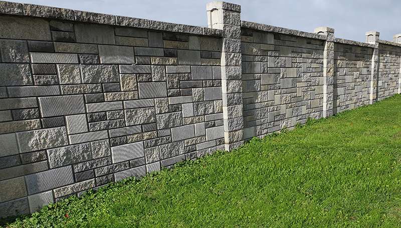
Inspired by the city walls of ancient civilizations, the AB® Fence is a mortarless concrete block fencing system that uses maintenance free interlocking blocks to create an attractive and effective solution for sound abatement, security, privacy and more.  

The AB® Fence system transfers wind loads horizontally to posts through interlocking fence panel units and integral bond beams to create post and panel sections. Ultimately, the loads are transferred from the posts to the supporting footings. However, the actual footing requirements are minimal compared to traditional cast-in-place fence designs with the entire load of the AB® Fence being resisted by footings only at the posts.  Only a small levelling pad is required beneath the fence panel since the panels can move and flex with any soil movement.    

The stabilising foundation to the entire AB® Fence system is a reinforced concrete footing. Footings can be designed in many different styles, but they all are intended to resist the lateral and vertical applied forces.  The typical AB Fence footing is a 600 mm diameter concrete pile footing utilising simple vertical steel reinforcement directly under the post. The site-specific parameters such as soil strength and wind loading will determine the design diameter, depth of each pile hole and the size or amount of rebar.  By increasing the pile footings diameter, depth or reinforcement schedule, the capacity of the footing can be increased.  

The AB® Fence system is a versatile product that can be built for a number of configurations. It is a system that provides flexibility to your design challenges and site constraints.  No matter what type of footing your project requires, an Allan Block Fence application can provide the solution you are looking for at a cost-effective price.

BENEFITS OF CHOOSING THE AB® FENCE SYSTEM

The benefits of using the AB® Fence system compared to other available fence or barrier wall systems are multiple and varied:

Aesthetics: With a crisp, clean architectural look, the AB® Fence system offers many different looks and style options by incorporating blocks with different colours and textures. Multiple shaped units can be used to create beautiful AB Ashlar Blend patterned fence panels.

Design flexibility: The design possibilities are endless while using the AB® Fence. The product can integrate curves and corners and adjust for the grade changes of your site with ease. The system will work with any type of foundation system that is properly designed to adequately handle the overturning moments required for the project. 

It can be designed to perform as a retaining wall and/or as a sound wall to mitigate and reduce noise pollution.

Durability: Concrete structures per se are durable and stable, providing a lifespan that is actually two or three times longer than other common materials. Most importantly, the system is maintenance free and less susceptible to water damage, fire, or decay that timber or wood fences.

Fully engineered: Both structural and sound testing have been conducted on the AB Fence® system to prove the load carrying capabilities and sound absorption properties of it.

Cost-effective: While the AB® Fence system might not be as economical as the traditional and popular timber fences, but it is extremely competitive when compared to pre-cast concrete and handcrafted stone masonry walls, as its easy installation saves time and money.

REFERENCES

Allan Block Corporation, “Installation Manual for Allan Block® Fence System”, 2013

Allan Block Corporation, Technical newsletter 16 “AB Fence – A sound choice”, 2012

Allan Block Corporation, Technical newsletter 23 “Elevated field created design challenges”, 2014

Allan Block Corporation, Technical newsletter 40 “Total site solutions – Walls and fence retaining”, 2018

John Desmond Limited. (n.d.). The history and meaning of fences https://www.johndesmond.com/blog/design/history-meaning-fences/

The secrets of no-fines concrete (NFC) on segmental retaining walls (SWR’s)

In recent years there has been an increasing demand for Allan Block® and Rocklok® retaining walls designed and built using No-fines Concrete (NFC). Sometimes called pervious concrete or porous concrete, NFC is essentially a special type of concrete containing little or no fine aggregate, such as sand.

As explained on the previous technical blog, the maximum wall height that can be constructed using the Allan Block® or Rocklok® retaining wall systems is directly proportional to their weight, width, inter unit shear strength, and vertical batter of construction for any given soil and site geometry conditions. NFC can be used to create a deeper and heavier concrete mass, augmenting the retaining wall resistance against external stability forces such as sliding and overturning. This will allow the maximum wall height of a simple gravity wall to be exceeded, facilitating taller and safer retaining walls with minimum excavation, faster construction, and lower labour costs.

NO-FINES CONCRETE PROPERTIES

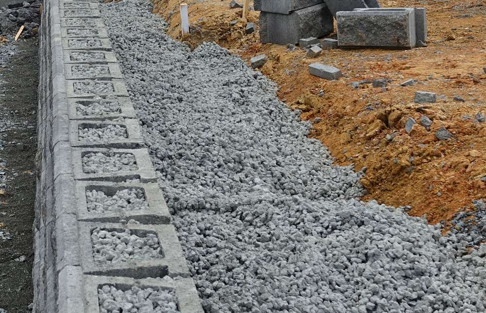
NFC is a combination of coarse aggregate, cement, and water, obtained by omitting fine aggregate from conventional concrete. The NFC has properties such as zero-slump, and it will exert similar pressures on the Allan Block® and Rocklok® blocks as loosely placed aggregate until cured.

The NFC should be made from carefully controlled amounts of water and cement with a ratio between 0.45 to 0.55, being the typical amount of cement 210 kg/m3. Using an average single-sized coarse aggregate of 20mm, surrounded and held together by the cement paste, creates a substantial 20% to 30% void ratio, making the mixture free draining.

A 6:1 gravel to cement ratio should provide a compressive strength exceeding 10MPa, which would be used for design purposes. Depending on the density of the coarse aggregate used, the NFC density should fall between 1,600 kg/m3 to 2,160 kg/m3.

Testing conducted on samples of NFC by Allan Block Corporation determined an average internal friction angle of 77.2°.

ADVANTAGES OF NO-FINES CONCRETE

Possibly the main advantage of using NFC is that it allows for taller gravity walls with less excavation and space maximisation. A common NFC depth is 40% to 50% of total wall height, while a geogrid reinforced retaining wall of the same height would require the geogrid length to be around 60% to 70% of total wall height. Occasionally a NFC base width greater than 50% may be required when the retaining wall is supporting high loads, steep backslopes are present, and for poor soil conditions.

From an operational point of view, the use of NFC simplifies the construction process and removes the necessity for compaction, compaction testing and heavy equipment on-site. NFC eliminates the need of having to import a well-graded backfill material and geogrid rolls, but it also removes the need of drainage metal within the Allan Block® or Rocklok® cores and behind the wall facing. The NFC is already highly permeable, providing a much higher drainage capacity as the entire mass if porous, dissipating hydrostatic pressure behind the wall.

In addition, NFC provides design flexibility when there are various site obstacles and constrains such as, property boundaries, tight corners or areas, manholes, and so on. 

CONSTRUCTION TIPS WHEN USING NFC

NFC must be used to fill both all the open core/cavities and spaces between Allan Block® or Rocklok® units and behind the blocks as backfill to the specified depth. However, the absolute minimum NFC depth should be not less than 600mm (including the SRW units’ width).

The recommended vertical lift of a pour should not exceed 600mm or three courses of blocks, although we suggest a vertical lift of 400mm as it will allow the contractor to comfortably rod the NFC into the cores of the lower courses making sure the cavities are full. Although the concrete pour will start to cure right after being placed, allowing for 2 to 3 hours between pours will help get higher aggregate stability, especially when building retaining walls over 1.2 metres in height. It is extremely important to brush off any material excess or concrete on top of the Allan Block® or Rocklok® units before it dries as it can affect the next course installation and the wall vertical and horizontal alignment.

To improve the anchorage of the Allan Block® or Rocklok® units to the NFC mass, it is suggested for straight wall sections that we remove one back wing per block as this will allow the NFC pour to flow into the spaces between units and lock the other wing securing the block wall facing.

Figure 3: Remove one wing per unit

When finishing the retaining wall and before placing the 200mm of low permeable soil on top of the NFC structure, a layer of geotextile/filter fabric needs to be horizontally placed on top of the NFC mass to prevent the settlement and migration of fines particles and to avert the NFC from clogging up. 

REFERENCES

1. Allan Block Corporation, “AB Commercial Installation Manual for Allan Block® Retaining Walls”, 2019

2. Allan Block Corporation, Tech Sheet 417 “Building with No Fines Concrete”, 2017

3. Bowers Brothers Concrete, “Rocklok® Installation Manual”, Revision B, 2021

4. Bowers Retaining Systems, “Rocklok® Engineering Manual,” Revision A, 2018

5. Braun Intertec, “No Fines Concrete Internal Angle of Friction Testing”, 2015

6. National Concrete Masonry Association, SRW History Article Series “SRW Design”, 2013

Mind your Gravity Wall

bowers-allan-block

A Simple Gravity Wall or just a Gravity Wall is a type of retaining wall that relies purely on its own self-weight to retain the soil behind and resist external forces. 

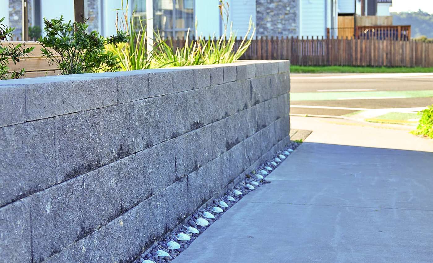
Typically made with heavy materials such as stones, poured concrete or masonry units, they can be constructed using simple or multiple depth units, and there are a multitude of systems available in the New Zealand market; small Segmental Retaining Walls (SRWs) such as Allan Block® and Rocklok®, gabion baskets, crib walls, stone walls, just to mention a few.

Among the SRWs systems, the large majority of them are low height walls used in landscaping and DIY projects for a wide variety of purposes; enhance aesthetics, create a flat level garden area, make a slope useful, reduce erosion and/or improve site drainage. 

Experience tells us that most gravity walls used for landscaping do not require engineering or a statement of opinion from a competent design professional (Producer Statement), so their design, construction and Building Code compliance is typically left to the skillful and astute contractor or homeowner. 

On most occasions, gravity walls are simple and straightforward, however, better to keep the following 7 things in mind when building your gravity wall.

1. HEIGHT

The maximum wall height that can be constructed using the Allan Block® or Rocklok® retaining wall systems is directly proportional to their weight, width, inter unit shear strength, and vertical batter of construction for any given soil and site geometry conditions.

Gravity walls rarely fail in sliding as the overturning calculations generally controls the maximum design height possible. Generally, most SRWs products can be comfortably built up to 900 millimetres without major complications or considerations providing that they are not excessively surcharged and that they are founded on good ground as defined by NZS 3604:2011. 

If a higher wall was required, using the SRW units in conjunction with No-Fines Concrete (NFC) will help create a deeper and heavier concrete mass, augmenting the retaining wall resistance against external stability forces such as sliding and overturning.

2. WALL BATTER

The extent the wall slopes backwards into the bank is referred as setback or wall batter, and gravity wall design is very sensitive to it. 

Although the client’s desired aesthetics and appearance are an important factor when selecting SRW units, we need to keep in mind that battering the retaining wall enhances stability as it moves the centre of gravity back from the toe of the wall and that it also reduces the earth pressure applied to the wall from the soil it is retaining. As the setback increases so it does the maximum height the gravity wall can be built. 

Typical setback angles are the 1° of Rocklok® to the 6° of the AB Classic or AB Junior units, being the AB Vertical somewhere in between as it provides a 3° angle from the vertical.

 3. SURCHARGES

The extent the wall slopes backwards into the bank is referred as setback or wall batter, and gravity wall design is very sensitive to it. 

Although the client’s desired aesthetics and appearance are an important factor when selecting SRW units, we need to keep in mind that battering the retaining wall enhances stability as it moves the centre of gravity back from the toe of the wall and that it also reduces the earth pressure applied to the wall from the soil it is retaining. As the setback increases so it does the maximum height the gravity wall can be built. 

Typical setback angles are the 1° of Rocklok® to the 6° of the AB Classic or AB Junior units, being the AB Vertical somewhere in between as it provides a 3° angle from the vertical. 

4. BACKSLOPES

The presence of slopes at the top of the retaining wall can substantially increase and even double the lateral earth pressures, creating instability on the retaining structure. Broken backslopes (slopes that crest and level off) will exert less pressure than steep continuous slopes, so they are less of a problem. 

Generally, most Allan Block® and Rocklok® gravity walls will perform very well with batter slopes lesser than to 1V:5H (11.3 degrees). Steeper back slopes might be feasible, but they should be evaluated.

 5. SOIL PROPERTIES & FOUNDATION STABILITY

Soils have an enormous influence on retaining walls. Clay soils are very common in many parts of New Zealand, but they can be challenging as they retain the water that filters into it, adding weight and increasing the pressure on the gravity wall. They are also susceptible to swelling and shrinkage.

The ideal soil to be used within and behind modular concrete block units is a clean, permeable, compactible, well-graded gravel or sand, preferably a material that provides weight to the blocks and allows water to pass through, such as drainage metal. 

Foundation stability is also key, so foundations soils should be adequately compacted before starting the construction of your Allan Block® and Rocklok® gravity walls, especially if the soils underneath have previously been disturbed, dug, imported, or substituted. For the levelling pad, the best options are probably an aggregate such as GAP 20 or GAP 40 as they are easy to compact and provide a high frictional and shear resistance to form a good foundation material.

6. WATER MANAGEMENT

Water is the number one enemy of any SRW, and it is the primary cause of failure. Localised sources of water must be considered when building any gravity wall, and surface water should be diverted away from the back of the wall using swales or berms.

Good drainage is essential for the longevity of the gravity wall, so all Allan Block and Rocklok® units should be filled with drainage rock. At the same time, it is convenient to place a minimum of 300 mm of the same selected material behind the SRW units to create what it is called “drainage column”. 

At the bottom of that drainage column a minimum Ø100 mm slotted or punched drainage pipe has to be located and vent to daylight to filtering incidental water and release hydrostatic pressure.

7. COUNCIL REQUIREMENTS

As previously stated, most gravity walls will not require engineering or a building consent as they generally retain less than 1.5 metres of ground. However, if the gravity wall height is under 1.5 metres and support any sort of surcharge or has a sloping ground above the wall a building consent might be required. Even when a building permit might not be needed, do not forget that all gravity walls must comply with the Building Code requirements. 

Finally, when the gravity wall is located on a boundary most local councils would require a 5 KPa or 12 kPa boundary surcharge loading, which will definitely influence your ability to build the wall as a gravity wall and on its compliance. 

 Bowers Brothers Concrete recommends engineering advice to be sought for walls exceeding 900 mm or positioned near a boundary.

REFERENCES

1. Auckland Council, AC2231 (v.2) “Construction of Retaining Walls”, 2014
2. Allan Block Corporation, “AB Engineering Manual Allan Block Retaining Walls”, 2014
3. BRANZ, Build 152, “Low Retaining Walls”, February/March 2016
4. Hugh Brooks and John P. Nielsen, “Basics of Retaining Wall Design: A design guide for earth retaining  structures”, Tenth Edition, 2013
5. IPENZ, Practice Note 1, “Guidelines on Producer Statements”, Version 3, 2014
6. National Concrete Masonry Association, “Segmental Retaining Walls Best Practices Guide for the Specification, Design, Construction and Inspection of SRW Systems”, 2016
7. New Zealand Standard 3604: 2011, “Timber-framed buildings”, 2011

At the Concrete Core!

Introduction

Quality is one of those generic, vague, and overused terms that most companies employ to highlight a degree of higher excellence or even superiority on their product and services. Everyone expects quality, whether it is of a new smartphone, a pair of jeans or the delivery of a meal at your doorstep. The criteria for measuring quality normally depend on the context and to be honest there is no single company in the world that would bring attention to their inferior or mediocre quality products and services if that was the case. This way the term quality does not have much value without benchmarking, to put it in other words, unless your product is measured, evaluated, and compared to the industry standards.

In New Zealand we have Standards New Zealand, which is an independent business unit within the Ministry of Business, Innovation and Employment (MBIE), which produce a range of standards, technical specifications, and codes of practice, which help deliver better value, greater economic efficiency, and that create a safer and more sustainable environment for all New Zealanders.

Concrete Masonry units and specifically Segmental Retaining Wall (SRW) units are required to meet the requirements of joint Australian/New Zealand standards; AS/NZS 4455.3:2008 and AS/NZS 4456:2003. In turn, if we would like to determine the Unconfined Compressive Strength of any Bowers Brothers concrete masonry units, we would need to refer exactly to AS/NZS 4456.4:2003, which sets the methods, requirements, and procedures to follow.

When talking about the compressive strength of our masonry units and our quality assurance and control processes, we can say the answer lies at the core.

Minimum Unconfined Compressive Strength

The Unconfined Compressive Strength test is a required property of concrete to control product integrity, and it is normally gauged in megapascals (MPa). A megapascal is simply a pressure measurement unit that represents force divided by area, and it is normally defined as N/mm2. The word pascal is named in honour of the French mathematician, philosopher, and physicist Blaise Pascal.

Some of the most popular SRW systems in the market, Allan Block® or Rocklok®, are based on hollow core units as the hollow cores reduce their product weight, freight charges and manufacturing costs. The local relevant standard, AS/NZS 4455.3:2008, suggests a minimum characteristic Unconfined Compressive Strength of just 10 MPa for retaining walls lower than 1.5 metres, and 12 MPa when the retaining wall height is between 1.5 metres and 10 metres. International standards such as ASTM C1372-17, usually require higher compressive strength values than those listed above, for example, the minimum requirement for compressive strength is 17.2 MPa on individual SRW units and 20.7 MPa on an average of three SRW units.

The introduction of the Rocklok® Retaining Wall system to the highway and infrastructure market required even higher quality control standards and product scrutiny to guarantee the product meets the New Zealand Transport Agency (NZTA) project specifications. For instance, the Te Ahu a Turanga: Manawatū Tararua Highway project highlights that all Rocklok® Retaining Wall blocks shall have a minimum 28-day compressive strength of 30 MPa.

Determining Unconfined Compressive Strength

Unless detailed on the project specifications, the minimum number of specimens required to determine the Unconfined Compressive Strength of concrete masonry products and in this case, the Unconfined Compressive Strength of the Rocklok® Retaining Wall System blocks, are 10 units for individual test in accordance with AS/NZS 4456.1:2003.

As more than 4,000+ units can be manufactured in a single production day, one of the key points of sampling is to ensure that the Rocklok® Retaining Walls units are selected from the lot in a well-distributed manner, this way sample units are carefully chosen and withdrawn at random intervals from the Columbia machine during the production day making it an accurate representation of the whole lot. On most occasions, a lot is defined as a full day of manufacturing, but that might change depending on what the client requesting the sample considers appropriate.

To simplify the process, usually the preference is to test whole Rocklok® Retaining Walls units, but that it is not as simple as it seems due to the difficulty in finding testing machines with enough loading capacity in the New Zealand market, so manufacturers must rely on part-units or drilled concrete cores, which is the case on the heavy duty Rocklok® Retaining Walls units.

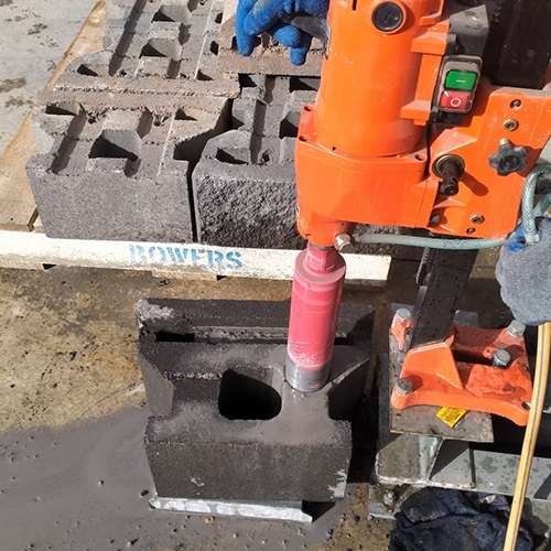
The test cores are obtained by using a diamond core drill ensuring that the action is performed in such a way that the concrete cores are not weakened by mechanical shock or by heating, so water is introduced to the process as a cooling fluid.

Each cylindrical core extracted from a Rocklok® unit is uniquely identified by marking on them a number and the correspondent lot number. Once the required 10 units are obtained, they are carefully submerged in a temperature controlled curing bath (21°C ± 2°C), avoiding any source of contamination and damage. The samples are later delivered to a third-party independent laboratory with just enough time to be tested at the required 28-days.’

To complete the process, each cylindrical core is trimmed to a length to diameter ratio greater than 2, capped and placed in a compression testing machine and subjected to increasing loading until it fails. Because of the destructive nature of the test, each specimen is only used once. From the maximum load and the known cross-sectional area resisting the load, the Unconfined Compressive Strength is calculated and plot.

At the Concrete Core!